Architectural Roof Ventilation: Balanced Net Free Area, Ridge Vents & Ice Dam Prevention
Building science of roof ventilation: 1:150 vs 1:300 Net Free Area (NFA) rules, baffled ridge vents, continuous soffits, and stopping catastrophic winter ice dams.

| Ventilation Technology | Net Free Area (NFA) | Operating Energy Cost | Weather Resistance Rating | Short-Circuit Risk |
|---|---|---|---|---|
| Externally Baffled Ridge Vent | 18 – 20 sq. in. / lin. ft. | $0.00 / year (Passive Stack) | High (TAS 100-A Wind-Driven Rain) | Zero (Continuous along peak) |
| Continuous Perforated Soffits | 10 – 12 sq. in. / lin. ft. | $0.00 / year (Passive Intake) | High (Perforated insect screen) | Zero (Mandatory intake baseline) |
| Gable End Triangular Louvers | Fixed (150 – 300 sq. in.) | $0.00 / year (Passive Cross-Air) | Moderate (Wind-driven rain leaks) | Severe (Short-circuits ridge vents) |
| Powered Roof Ventilator (PAV) | Active Fan (1,000+ CFM) | $150 – $300 / year (Electric) | Moderate (Mechanical motor seals) | Extreme (Backdrafts flues & pulls rain) |
Executive Architectural & Engineering Overview: The Thermodynamic Breathing Attic
In high-performance residential building science, an attic is never an inert storage vault; it is a dynamic thermodynamic heat exchanger and moisture accumulator. Every single day, an attic must process immense volumes of heat energy and water vapor generated by both exterior solar radiation and interior human living activities. If this energy is not continually exhausted through an engineered airflow strategy, the roof assembly suffers severe degradation: shingle embrittlement, winter ice damming, structural truss mold blooms, and catastrophic energy penalties.
When designing or retrofitting a residential roof, architects and master builders encounter a widespread misconception: the belief that adding any random vent will improve ventilation. In reality, uncoordinated ventilation is worse than no ventilation at all. A high-performance roof requires an engineered Balanced Net Free Ventilation Area (NFA) system that coordinates continuous intake at the eaves with continuous exhaust at the ridge:
- Continuous Low-Eave Intake: Drawing cool, dry exterior ambient air into the lowest point of the roof assembly through continuous perforated soffit vents.
- Continuous High-Ridge Exhaust: Expelling superheated, humid attic air at the highest point of the roof structure through externally baffled continuous ridge vents.
- The Convective Stack Effect: Utilizing natural thermodynamic buoyancy (warm air rises naturally due to lower molecular density) to create an automated, zero-electricity convective air pump that flushes the roof deck 24 hours a day.
- Prevention of Short-Circuiting: Eliminating the dangerous practice of mixing powered attic ventilators (PAVs), gable louvers, and ridge vents, which disrupts laminar airflow and pulls weather into the home.
- Forensic Ice Dam Mitigation: Decoupling interior building heat loss from the cold roof deck to eliminate the freeze-thaw cycles that create destructive winter ice dams.
A roof does not fail from rain hitting its shingles; a roof fails from heat and moisture suffocating its underside. An engineered attic is a breathing thermodynamic diaphragm that protects the structural envelope indefinitely.
By understanding the fluid dynamics of air exchange, international building code formulas, and heat transfer physics, homeowners and architects can safeguard their residential investments against structural rot and expensive energy loss.
---
Thermodynamic Physics: The Convective Stack Effect & Net Free Area Math
Attic ventilation operates on two fundamental physical principles: Thermal Buoyancy (The Stack Effect) and Wind-Induced Pressure Differentials (The Bernoulli Principle).
The Thermal Stack Effect Formula
Air density decreases as its temperature rises. Warm air expands, becomes lighter than surrounding cool air, and exerts upward buoyant pressure: $$\Delta P = C \cdot h \left( rac{1}{T_o} - rac{1}{T_i} ight)$$
- Where $$\Delta P$$ is the buoyant pressure differential, $$h$$ is the vertical distance between the intake soffit and the exhaust ridge, $$T_o$$ is the absolute outdoor temperature, and $$T_i$$ is the internal attic temperature.
- In a steep-slope roof (8:12 to 12:12 pitch) with a 15-foot vertical height between soffit and ridge, a 40°F temperature differential generates continuous convective air velocity exceeding 150 to 250 feet per minute (FPM) without any mechanical fans or electrical power consumption.
+-------------------------------------------------------------------------+
|                  THE THERMODYNAMIC ATTIC STACK EFFECT                   |
+-------------------------------------------------------------------------+
                     [CONTINUOUS BAFFLED RIDGE VENT]
                               ▲        ▲
                               │ EXHAUST│ (Hot, Humid Air Escapes at Peak)
                               │        │
                     ┌─────────┴────────┴─────────┐
                     │ \                        / │
                     │   \   ATTIC CAVITY     /   │
                     │     \  (Continuous   /     │
                     │       \ Air Wash)  /       │
                     │         \        /         │
  [PERFORATED SOFFIT] ───────►   \    /   ◄─────── [PERFORATED SOFFIT]
  (Cool Exterior Intake)          └──┘             (Cool Exterior Intake)
+-------------------------------------------------------------------------+
The Code Mandate: The 1:150 Rule vs. The 1:300 Exemption
Under Section R806.1 of the International Residential Code (IRC), the minimum net free ventilating area shall be:
- The Baseline 1:150 Rule: One square foot of Net Free Area (NFA) for every 150 square feet of attic floor area.
- The 1:300 Code Exemption (IRC Section R806.2): The ventilation ratio can be reduced to 1:300 if two strict criteria are met:
- In Climate Zones 6, 7, and 8, a certified Class I or Class II vapor retarder (perm rating < 1.0) is installed on the warm-in-winter side of the ceiling insulation.
- Between 40% and 50% of the total required ventilating area is provided by ventilators located in the upper portion of the attic space (at least 3 feet below the ridge), with the balance provided by eave or cornice vents.
Sizing Symmetrical Net Free Area (The 50/50 Balance Ratio)
Air cannot leave an attic if air cannot enter. A high-performance ventilation system strictly enforces a 50% Intake / 50% Exhaust balance, or a slight positive bias toward intake (60% Intake / 40% Exhaust):
- *Example Calculation*: Consider a 3,000-square-foot attic footprint under the 1:300 rule:
$$ ext{Total Required NFA} = rac{3,000 ext{ sq. ft.}}{300} = 10.0 ext{ sq. ft. of NFA (1,440 sq. inches)}$$
- Applying the 50/50 rule:
- - Required Intake at Soffits: $$1,440 imes 50 = 720 ext{ square inches of NFA}$$
- - Required Exhaust at Ridge: $$1,440 imes 50 = 720 ext{ square inches of NFA}$$
- If a continuous ridge vent delivers 18 square inches of NFA per linear foot, the roof requires:
$$ ext{Linear Ridge Length} = rac{720}{18} = 40 ext{ linear feet of continuous ridge vent}$$
- Symmetrically, with an 80-foot aggregate eave perimeter, the continuous soffit vents must provide at least $$720 / 80 = 9 ext{ sq. in. of NFA per linear foot}$$.
---
Architectural Hardware: Ridge Vents vs. Soffits vs. Power Ventilators
Selecting the appropriate venting hardware is critical for avoiding catastrophic airflow imbalances.
| Venting Hardware Typology | Net Free Area (NFA) Rating | Aerodynamic Mechanism | Failure Risk / Architectural Vulnerability | |---|---|---|---| | Externally Baffled Ridge Vent (Shingle-Over) | 18 – 20 sq. in. / linear ft | Convective stack effect + external wind baffle creates low-pressure vacuum suction (Bernoulli effect). | Unbaffled vents allow wind-driven rain and snow infiltration. | | Continuous Perforated Aluminum Soffit | 9 – 12 sq. in. / linear ft | Low-pressure intake wash running full perimeter of eaves. | Clogged by blown-in cellulose or fiberglass insulation if baffles are missing. | | Gable End Louvers (Triangular/Rectangular) | Fixed area (typically 150 – 300 sq. in.) | Passive cross-ventilation across upper attic volume. | Creates stagnant air pockets in cathedral peaks; disrupts ridge vent suction. | | Powered Attic Ventilators (PAVs - Electric/Solar) | 800 – 1,600 CFM motorized fan | Motorized active evacuation via roof-mounted fan. | Severe Hazard: Depressurizes attic, sucking conditioned air from living space. |
The External Air Deflection Baffle
A continuous ridge vent must feature an external vertical air baffle:
- When horizontal wind strikes the roof, it hits the external baffle and is deflected upward over the ridge.
- According to the Bernoulli Principle, high-velocity air moving over the baffle creates a localized negative pressure zone (vacuum suction) directly over the exhaust slots.
- This vacuum actively pulls warm, moist air out of the attic even on days with zero internal thermal stack effect.
- Unbaffled ridge vents lack this external lip. When wind blows against an unbaffled vent, the wind forces its way *into* the vent, blowing rain and snow backward into the attic while completely stalling convective exhaust.
---
The Fatal "Short-Circuiting" Error: Mixing Exhaust Typologies
The most prevalent architectural error in roof remodeling is the dangerous assumption that "more vents equal better ventilation." Contractors routinely install new continuous ridge vents while leaving existing gable end louvers open, or worse, adding a motorized roof fan.
The Physics of Short-Circuiting
Air follows the path of least physical resistance. For an attic ventilation system to function, air must enter at the lowest point (the eaves) and travel continuously across the entire underside of the roof sheathing to the peak:
- When a contractor installs a continuous ridge vent on a home with open gable end vents, the low-pressure suction of the ridge vent does not pull air from the distant soffits.
- Instead, the ridge vent draws air directly from the nearby gable vents located mere feet away at the end of the roof.
- The Consequence: A localized short-circuit air loop forms at the peak of the gable walls. The entire lower two-thirds of the roof deck receives zero fresh air wash. Stagnant, moist air pools in the lower rafters, leading to massive fungal mold blooms and rot directly above the exterior walls.
+-------------------------------------------------------------------------+
|                  THE SHORT-CIRCUITING AIR DISASTER                      |
+-------------------------------------------------------------------------+
                     [CONTINUOUS RIDGE VENT]
                               ▲
                               │ (Exhausts Air)
                               │
                ◄──────────────┴──────────────►
               / (Short-Circuit Air Loop)                    /                                   [GABLE END VENT] ──(Air Enters Here)           [GABLE END VENT]
       │
       ▼
  *STAGNANT AIR ZONE (LOWER TWO-THIRDS OF ROOF)*
  - Zero Airflow from Soffits
  - Moisture Accumulates
  - Severe Sheathing Mold & Wood Rot
  - Ice Dams Form at Eaves
+-------------------------------------------------------------------------+
The Powered Attic Ventilator (PAV) Hazard
Installing an electric or solar-powered attic ventilator on a roof with a ridge vent is an engineering disaster:
- A 1,200 CFM motorized fan requires massive incoming airflow. Because standard soffit vents cannot provide 1,200 CFM instantly, the fan creates an intense negative vacuum inside the attic.
- The fan begins sucking air backward through the ridge vent, pulling rainwater and snow down into the attic.
- Even worse, the powerful vacuum pulls conditioned, air-conditioned or heated air out of the living space below through ceiling light fixtures, recessed cans, and attic access hatches, dramatically increasing home heating and cooling bills by 20% to 30%.
---
Winter Ice Dam Physics & Comprehensive Forensic Mitigation
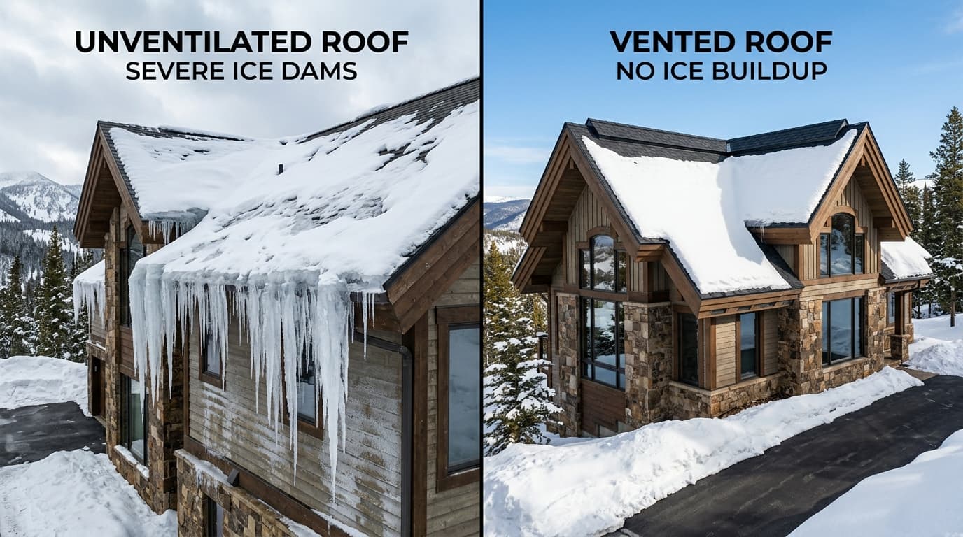
In cold climate zones (ASHRAE Climate Zones 5 through 8), ice dams represent the single most destructive winter failure mode in residential construction.
The Thermodynamic Mechanism of Ice Dam Formation
Ice dams are not caused by cold outdoor weather; ice dams are caused by uncontrolled heat escaping from the living space into the attic:
- The Melting Phase: Heat escaping through unsealed ceiling penetrations (recessed lights, bathroom exhaust ducts, chimney chases) warms the attic air. This heat conducts through the structural rafters, warming the upper roof deck sheathing to temperatures above 32°F (0°C).
- The Runoff Phase: Snow resting on the upper warm roof deck melts into liquid water. The melted snow runs downward along the roof surface beneath the snow blanket toward the eaves.
- The Freezing Phase: When the liquid runoff reaches the exterior eaves and overhangs (which extend past the exterior wall of the home), there is no warm attic beneath it. The eave sheathing is at the ambient outdoor freezing temperature (e.g., 15°F to 20°F).
- The Dam Formation: The runoff immediately freezes upon hitting the cold eave, forming an initial ice ridge. Over days of melting and refreezing, this ice ridge grows into a massive, solid ice dam several inches thick.
- The Water Intrusion: Melted water pools behind the ice dam. Because water cannot freeze through the dam, it creates a rising reservoir. Once the water level exceeds the height of the overlapping shingle tabs, water penetrates horizontally through capillary action, pouring into exterior wall cavities, soaking insulation, and collapsing interior drywall ceilings.
+-------------------------------------------------------------------------+
|                     THERMODYNAMIC ICE DAM MECHANISM                     |
+-------------------------------------------------------------------------+
   [SNOW BLANKET]
      │
      ├──> UPPER ROOF DECK: WARMED TO 36°F (Heat Loss from Living Space)
      │    *Snow melts into liquid water runoff*
      │    │
      │    ▼ (Water runs down slope beneath snow)
      │
      └──> COLD EXTERIOR OVERHANG: 15°F (No Heat from Below)
           *Water hits cold eave and instantly freezes into massive ICE DAM*
           *Pooled water backs up under shingles, destroying interior walls*
+-------------------------------------------------------------------------+
The Three-Part Forensic Cure:
- Air-Sealing the Ceiling Plane (Blower Door Guided): Seal all thermal bypasses between the living space and the attic: seal electrical wire penetrations with expanding fire-rated polyurethane foam, seal drywall tops to wall framing, weatherstrip attic pull-down stairs, and install airtight vapor-sealed can light enclosures.
- Deep Continuous Insulation (R-49 to R-60): Install high-density mineral wool or blown cellulose insulation across the entire attic floor to an R-value meeting the latest IECC standards, ensuring heat stays inside the living quarters.
- Continuous Baffled Air Wash: Install rigid structural ventilation baffles (such as AccuVent or Berger Raft-R-Mate) in every single rafter bay along the eaves. These baffles prevent blown insulation from clogging the soffits and ensure a continuous stream of freezing exterior air sweeps the underside of the roof deck, keeping the entire roof sheathing uniformly cold (below 32°F) from ridge to eave.
---
Itemized Cost Schedule & Regional Labor Breakdown
Upgrading an attic ventilation system to balanced architectural standards pays immediate dividends in shingle lifespan extension and ice dam elimination.
Comprehensive 2026 Budget Breakdown ($5,800 Total System Installation)
| System Component / Scope | Premium Materials & Hardware | Specialized Trade Labor | Total Cost | % of Budget | |---|---|---|---|---| | Continuous Baffled Ridge Vent (50 Lin. Ft.) | $450 (Air Vent ShingleVent II or GAF Cobra 3) | $850 (Roofers cutting slot, nailing cap shingles) | $1,300 | 22.4% | | Continuous Perforated Aluminum Soffits (120 Lin. Ft.) | $850 (Heavy-gauge vented aluminum panels & J-channel) | $1,400 (Siding mechanics custom retrofitting eaves) | $2,250 | 38.8% | | Rafter Baffle Insulation Chutes (36 bays) | $220 (AccuVent PVC rigid continuous wind baffles) | $450 (Attic mechanics stapling baffles to deck) | $670 | 11.5% | | Attic Air-Sealing & Bypass Foaming | $380 (Two-part expanding closed-cell foam kits) | $850 (Energy auditors foaming all wire/pipe penetrations) | $1,230 | 21.2% | | Decommissioning Obsolete Gable/PAV Vents | $50 (Plywood block-off panels & fasteners) | $300 (Carpenters sealing off old vents permanently) | $350 | 6.1% | | TOTALS | $1,950 | $3,850 | $5,800 | 100.0% |
Regional Labor Multipliers
- New York / New England / Chicago Metro: Multiply labor by 1.30x to 1.45x ($6,800 – $7,400 total).
- Denver / Minneapolis / Pacific Northwest: Multiply labor by 1.15x to 1.25x ($6,200 – $6,600 total).
- Midwest / Mid-Atlantic Non-Metro: Multiply labor by 0.85x to 0.95x ($5,100 – $5,400 total).
---
Step-by-Step Installation & Air Balancing Protocol
Executing a balanced ventilation retrofit requires following a strict, chronological sequence:
Phase 1: Pre-Retrofit Inspection & Attic Air-Sealing
- Conduct a comprehensive attic audit using a thermal imaging camera (such as a FLIR E8) to identify all ceiling thermal bypasses.
- Seal all electrical junction boxes, plumbing vent pipe penetrations, and chimney chases using two-component polyurethane foam and fire-rated sheet metal.
- Install an insulated, weatherstripped cover box (minimum R-30) over the attic pull-down stair hatch.
Phase 2: Rafter Baffle Chute Installation
- Working from inside the attic, clean all debris away from the bird-mouth framing cuts at the exterior wall plates.
- Install rigid PVC rafter baffles (AccuVent or equivalent) in every single rafter bay. Fasten the baffles directly to the underside of the roof sheathing, extending at least 12 inches above the final finished insulation depth.
- Verify that the bottom cardboard or plastic flange of the baffle acts as a positive wind dam, preventing exterior winds from blowing through the soffits and displacing the loose attic insulation.
Phase 3: Soffit Intake Retrofit
- Remove old wooden soffit panels or solid vinyl trim along all eaves.
- Install continuous perforated aluminum or vinyl soffit panels delivering a minimum of 9 to 12 square inches of Net Free Area per linear foot.
- Secure the panels with corrosion-resistant stainless steel trim nails, ensuring zero gaps where insects or bats could enter.
Phase 4: Ridge Slot Cutting & Baffled Vent Installation
- Snap chalk lines along the roof peak. Cut a continuous 1-3/4 inch slot (7/8 inch on each side of the ridge board) through the asphalt shingles and wood roof sheathing using a circular saw set to exact deck depth. Stop the cut 12 inches shy of gable end walls to preserve architectural weather margins.
- Center the continuous externally baffled ridge vent over the cut slot. Fasten the vent sections using 2-1/2 inch hot-dip galvanized roofing nails.
- Install matching architectural cap shingles over the ridge vent, blind-nailing with corrosion-resistant fasteners.
Phase 5: Decommissioning Competing Exhausts
- Permanently block off all old gable end louvers, mushroom pot vents, and motorized power fans using 1/2-inch CDX plywood screwed from inside the attic, sealed airtight with silicone caulk.
---
Forensic Failure Analysis: Five Critical Attic Ventilation Defects
Forensic building envelope investigators routinely trace catastrophic structural failures to un-engineered attic ventilation.
1. The Winter "Attic Rain" Phenomenon
- Physical Manifestation: Water dripping profusely through ceiling light fixtures during a sunny, freezing winter morning, mimicking a severe roof leak when there is zero rain.
- Root Forensic Cause: Warm, humid air from bathroom showers leaked through unsealed attic penetrations into a freezing, poorly ventilated attic. The moisture froze into a solid layer of white rime frost across the underside of the plywood roof sheathing. When the sun struck the roof, the frost melted instantly, raining down across the ceiling insulation.
- Mandatory Preventative Engineering: Air-seal the ceiling plane; exhaust all bathroom fans directly through dedicated roof jacks to the exterior; ensure balanced continuous soffit-to-ridge airflow.
2. North-Facing Roof Deck Wood Rot & Fungal Blooms
- Physical Manifestation: Structural plywood sheathing turning black with *Aspergillus* or *Stachybotrys* mold colonies, delaminating into spongy wood pulp within 6 years.
- Root Forensic Cause: Inadequate low-eave intake caused by blown cellulose insulation blocking the soffits. Lacking fresh air exchange, humidity remained trapped against the colder, non-sunlit north roof slope.
- Mandatory Preventative Engineering: Install rigid rafter ventilation baffles in every rafter bay; maintain a verified 50/50 intake-to-exhaust NFA ratio.
3. Shingle Blistering & Premature Granule Loss
- Physical Manifestation: High-end architectural shingles developing small pimple-like blisters, cracking, and losing granules within 8 to 10 years of installation.
- Root Forensic Cause: Chronic attic superheating exceeding 150°F caused by absent ridge ventilation. The extreme heat baked the petroleum asphalt matrix from the underside, driving out volatile plasticizers.
- Mandatory Preventative Engineering: Size ventilation to the 1:150 or 1:300 IRC mandate; specify externally baffled ridge vents that drop attic peak temperatures by 40°F.
4. Wind-Driven Snow Infiltration
- Physical Manifestation: Several inches of fine powdered snow accumulating on top of attic floor insulation following a winter blizzard.
- Root Forensic Cause: Installing cheap, unbaffled continuous ridge vents. High-velocity winter winds pushed blowing snow straight through the open exhaust louvers.
- Mandatory Preventative Engineering: Install only externally baffled ridge vents featuring internal hydrophobic filter meshes (such as GAF Cobra or ShingleVent II) tested to pass the Miami-Dade County 110 mph wind-driven rain and snow standard (TAS 100-A).
5. Powered Attic Fan Backdrafting
- Physical Manifestation: Homeowners experiencing chronic headaches and nausea; carbon monoxide detectors alarming in utility rooms.
- Root Forensic Cause: A high-CFM powered attic ventilator depressurized the attic, pulling combustion gases backward down the atmospheric flue of a gas furnace or water heater.
- Mandatory Preventative Engineering: Eliminate motorized attic exhaust fans; rely exclusively on passive, self-balancing aerodynamic stack-effect ridge and soffit systems.
---
Real-World Architectural Case Studies
Case Study 1: The Heavy Snow Mountain Chalet — Duluth, Minnesota
- Architectural Scope: Complete roof and envelope overhaul of a 3,800 sq. ft. timber-framed mountain residence suffering from catastrophic winter ice dams.
- Engineering Dilemma: Winter temperatures average 5°F with heavy snow accumulations exceeding 60 inches. Massive 2-foot thick ice dams routinely formed along the eaves, tearing off gutters and causing $45,000 in ceiling drywall water damage over three winters.
- Applied Solutions:
- *Thermal Bypass Sealing*: Deployed two-part closed-cell polyurethane foam across the entire 3,800 sq. ft. ceiling plane, eliminating 100% of air leakage from the heated living quarters.
- *Deep Insulation & Baffles*: Installed AccuVent PVC baffles in all 72 rafter bays, topped with blown cellulose insulation achieving a true R-60 thermal barrier.
- *Balanced Ventilation*: Cut a continuous 1-3/4" ridge slot and installed 65 feet of Air Vent ShingleVent II baffled ridge vent, paired with continuous perforated aluminum soffits.
- Financial Tally: Total Project Expenditure: $18,200. Zero ice dams formed during subsequent record-setting winter snowfalls.
Case Study 2: The Sunbelt Cooling Optimization — Dallas, Texas
- Architectural Scope: Energy optimization retrofit of a 4,200 sq. ft. luxury Mediterranean home with high summer air conditioning utility bills exceeding $800/month.
- Engineering Dilemma: The home utilized an obsolete, noisy 1,600 CFM electric attic fan that was short-circuiting with two open gable louvers, leaving attic ambient temperatures hovering at a blistering 155°F on summer afternoons.
- Applied Solutions:
- *Decommissioning PAV & Gable Louvers*: Removed the motorized roof fan, permanently sealed off both gable end vents from the inside, and installed 80 linear feet of continuous baffled ridge vent.
- *Intake Enlargement*: Replaced narrow, painted-over soffit screens with high-capacity continuous perforated aluminum panels delivering 12 sq. in. NFA/foot.
- *Thermal Metrology*: Peak summer attic temperatures dropped from 155°F to 108°F (a 47°F reduction), slashing air conditioning electrical consumption by 22% ($175/month savings).
- Financial Tally: Total Project Expenditure: $6,400; Net 5-Year Energy Savings: $8,750.
---
Architectural Specification Guide: Master Division Standards
When drafting roof ventilation specifications, architects enforce MasterFormat Division 07 standards:
Division 07 72 00 — Roof Accessories & Ventilation
- Ridge Vents: High-density UV-stabilized polypropylene continuous ridge vent with external wind-deflection baffles conforming to ASTM D1929 and passing Miami-Dade County TAS 100(A) for wind-driven rain resistance. Minimum NFA: 18 sq. in. per linear foot.
- Soffit Intake Vents: Continuous perforated architectural-grade aluminum panels conforming to ASTM B209, finished in a fluoropolymer or polyester baked enamel finish. Minimum NFA: 10 sq. in. per linear foot.
- Rafter Baffles: Rigid, moisture-resistant PVC or high-density extruded polystyrene continuous chutes providing minimum 2 inches of clear, unobstructed airflow clearance beneath roof sheathing.
- Airflow Balance: Sized strictly to satisfy IRC Section R806.2, maintaining a minimum 50% low-eave intake to 50% high-ridge exhaust ratio.
---
General Contractor & Roofing Trade Vetting Guide
To ensure your home’s attic ventilation performs to rigorous building-science standards, apply strict vetting benchmarks:
Trade Vetting Checklist
- Net Free Area Calculation Verification: Ask the contractor: "Can you show me your mathematical calculation for Net Free Area balancing between the soffits and the ridge for our specific attic square footage?" If they cannot produce a simple mathematical equation, they are guessing rather than engineering.
- The "No Mixed Exhaust" Rule: Verify that the contractor’s scope of work explicitly includes blocking off old gable end louvers or mushroom pot vents when installing a new ridge vent.
- Baffle Chute Inspection: Require in the contract that the project manager inspect and photograph the rafter baffle chutes in the attic prior to blowing in loose insulation, ensuring zero soffit vents are smothered.
---
Frequently Asked Questions (Technical & Climate)
1. Why are ridge vents more effective than mushroom pot vents or gable vents?
A continuous ridge vent runs the entire length of the roof peak, creating a uniform, continuous air exhaust that flushes 100% of the rafter bays simultaneously. Individual mushroom pot vents or gable vents only pull air from their immediate vicinity, leaving wide dead zones in the attic where hot, humid air stagnates. Furthermore, an externally baffled ridge vent harnesses wind power (the Bernoulli Principle) to actively vacuum air out of the attic even when there is no wind or thermal stack effect.
2. Can you have too much attic ventilation?
In building science, you cannot have too much intake ventilation, but you can have improperly balanced exhaust. Having excessive exhaust with inadequate intake creates a dangerous negative vacuum inside the attic, pulling air-conditioned or heated air out of your living rooms through ceiling penetrations. As long as your intake (soffit) Net Free Area matches or slightly exceeds your exhaust (ridge) Net Free Area, high ventilation rates simply keep your roof cooler and drier with zero negative side effects.
3. Will snow block a continuous ridge vent in the winter?
While a heavy blanket of fresh snow may temporarily cover a ridge vent, warm air rising from the attic stack effect naturally melts a small channel through the snow cap within hours, re-establishing continuous airflow. Furthermore, externally baffled ridge vents are engineered with internal weather baffles and synthetic fiber filters that prevent blowing snow and blizzard drafts from infiltrating the attic.
4. Do solar-powered attic fans save money compared to passive ridge vents?
No. Independent building science research (conducted by the Florida Solar Energy Center and Home Innovation Research Labs) consistently shows that motorized solar attic fans provide negligible energy savings and frequently cause structural harm. Powered fans create an intense localized negative pressure that sucks conditioned air out of the home through ceiling bypasses, increasing air conditioning utility bills. A passive, balanced ridge-and-soffit system costs zero dollars to operate, requires zero electrical maintenance, and moves more air uniformly across the entire roof deck than a solar fan.
5. What is the difference between the 1:150 and 1:300 ventilation rule in building codes?
The International Residential Code (IRC Section R806) mandates a baseline ventilation ratio of 1 square foot of Net Free Area (NFA) for every 150 square feet of attic space (the 1:150 rule). However, building codes allow a 50% reduction to 1:300 if between 40% and 50% of the ventilation is positioned in the upper portion of the roof (such as a ridge vent) and the remaining 50% to 60% is positioned at the eaves (soffits), and an approved vapor retarder is present on the ceiling plane. The 1:300 rule encourages balanced, continuous high-low airflow.
6. Why did ice dams destroy my gutters even though I have heat cables installed?
Electric heat cables (zigzag wires) do not solve the root cause of ice dams; they simply melt narrow 2-inch tunnels through the ice, leaving the rest of the dam intact. Furthermore, heat cables consume significant electricity and often burn out without warning. Ice dams are caused by heat escaping from your home through unsealed attic floor leaks, warming the upper roof deck and melting snow that refreezes at the cold eaves. The only permanent, maintenance-free cure for ice dams is air-sealing the ceiling plane, adding deep R-60 insulation, and installing continuous rafter baffles to keep the roof deck uniformly cold.
7. How do I know if my soffit vents are blocked by insulation?
The easiest way to check is to enter the attic on a bright, sunny afternoon, turn off all work lights, and look down toward the lowest eaves where the roof meets the exterior wall. If your soffit vents are open and properly baffled, you will see a continuous line of bright daylight shining through the rafter bays. If the perimeter is pitch black or if you see mounds of fluffy pink fiberglass or gray cellulose packed tight against the roof sheathing, your soffits are completely smothered, and your attic is suffocating without fresh air intake.
Frequently Asked Questions
Written by Marcus Thorne
Master Builder & Construction Cost EstimatorMarcus has supervised over 250 ground-up custom luxury builds and full gut renovations across the United States. He translates complex general contractor contracts, construction line-item pricing, and municipal permitting into clear guidance for homeowners.
Related Research in Roofing & Exteriors
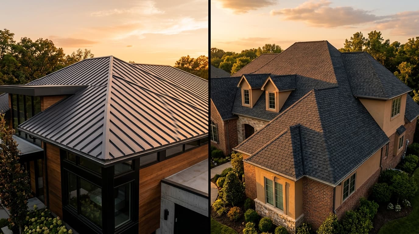
Standing Seam Metal Roof vs. Architectural Shingles: 30-Year Cost & Durability Breakdown
Compare 30-year lifecycle costs, wind ratings, thermal performance, and ROI between standing seam metal and architectural shingles.
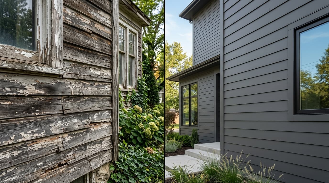
Fiber Cement vs. Engineered Wood vs. Natural Cedar Siding: Exterior Cladding Guide
Comprehensive siding evaluation: James Hardie fiber cement, LP SmartSide engineered wood, and Western Red Cedar. Flame spread, rot resistance, and maintenance.

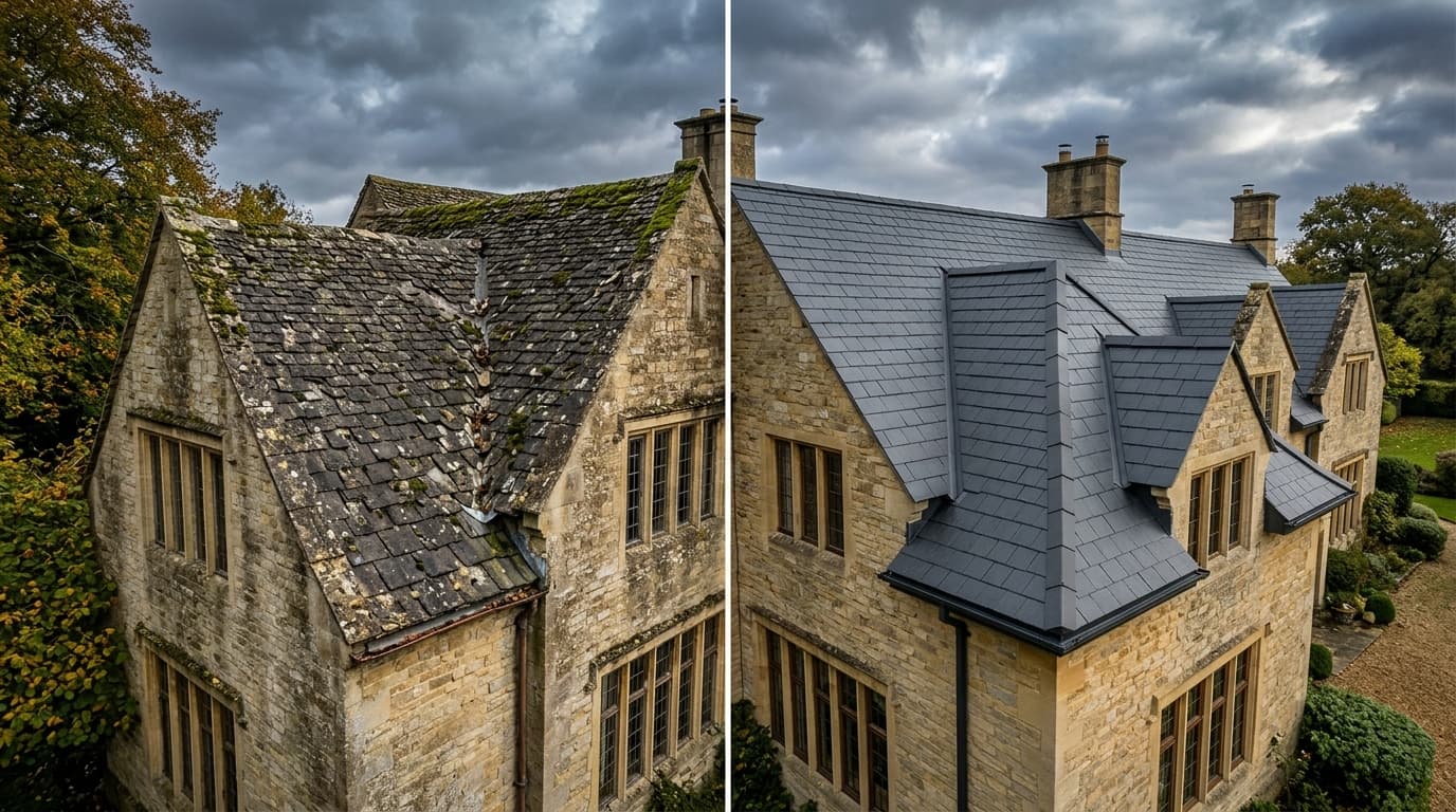
Natural Slate vs. Synthetic Composite Roofing: Architectural Weight, Cost & Framing
Evaluate natural quarry slate against synthetic composite slate (DaVinci): dead load structural engineering, 100-year lifespans, and installation costs.