Hydronic Radiant Floor Heating: Boiler vs. Air-to-Water Heat Pump Engineering
Design guide for in-floor hydronic radiant heating: PEX tubing layouts, manifold balancing, modulating gas boilers vs air-to-water heat pumps, and flooring compatibility.

| Mechanical Parameter | Mod-Con Gas/Propane Boiler | Air-to-Water Inverter Heat Pump | Traditional Forced-Air Furnace |
|---|---|---|---|
| Thermodynamic Efficiency | 95% – 98% AFUE (COP ~0.96) | COP 3.2 – 4.8 (320% to 480% eff.) | 80% – 96% AFUE |
| Distribution Mechanism | Gentle thermal radiation (<85°F floor) | Gentle thermal radiation (<85°F floor) | High-velocity convective air blast |
| Summer Cooling Capability | None (Requires separate AC system) | Reversible chilled water cooling | Separate AC condenser and coil |
| Acoustic Sound Level | 100% Silent (Zero moving air) | 100% Silent (Zero moving air) | 45 – 55 dBA (Noisy blower fan) |
| Allergen & Dust Agitation | Zero air movement / Hypoallergenic | Zero air movement / Hypoallergenic | High continuous dust circulation |
| Expected Infrastructure Life | PEX: 100+ yrs; Boiler: 20 yrs | PEX: 100+ yrs; Heat pump: 20 yrs | Ductwork: 20 yrs; Furnace: 15 yrs |
Executive Architectural & Engineering Overview: The Apex of Thermal Comfort
In luxury residential design, thermal comfort is often misunderstood as merely maintaining a set air temperature on a wall thermostat. However, human thermal comfort is not governed primarily by air temperature; it is governed by radiation. According to the fundamental principles of biophysical thermal comfort established by Ole Fanger and codified in ASHRAE Standard 55, the human body loses over 50% of its internal metabolic heat via thermal radiation to surrounding architectural surfaces (floors, walls, windows, and ceilings).
When a home utilizes traditional forced-air heating, the furnace blows hot, dry air (120°F to 130°F) into the room. Because warm air is buoyant, it immediately rises to the ceiling, leaving the floor cold. The occupant’s feet radiate heat into the cold floor while their head sits in overheated, dry air—a physiological condition that creates thermal discomfort, dry nasal passages, and chronic fatigue. Furthermore, high-velocity forced-air systems stir up dust, pet dander, and allergens continuously while generating intrusive fan noise.
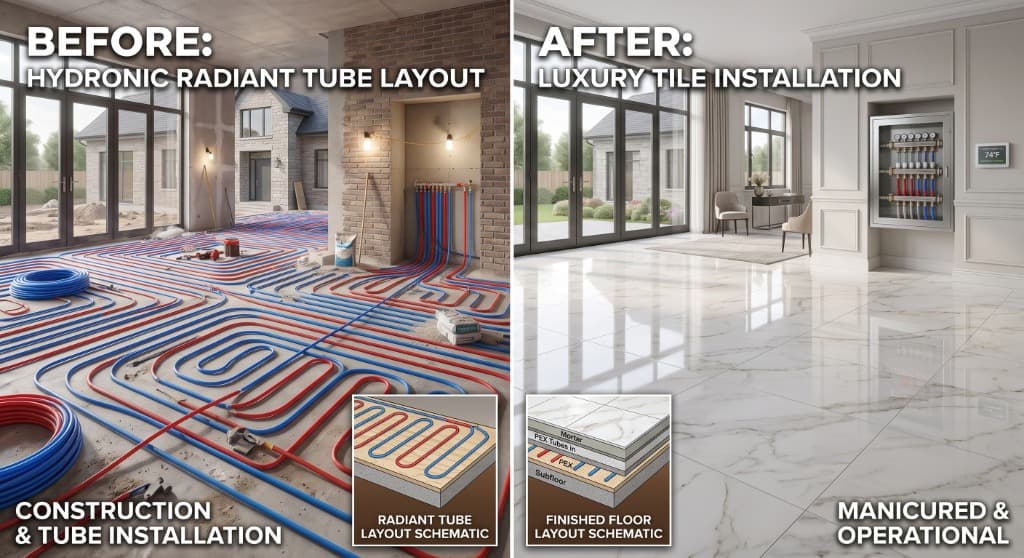
Hydronic In-Floor Radiant Heating represents the absolute pinnacle of architectural thermal engineering. By circulating warm water through an engineered network of cross-linked polyethylene (PEX-a) tubing embedded directly beneath the finished floor, the entire floor surface transforms into a gentle, silent, low-temperature thermal radiator:
- The Ideal Physiological Temperature Gradient: Warmer at the floor (75°F to 80°F) and slightly cooler at head level (68°F), perfectly matching human vascular thermodynamics.
- Zero Airborne Dust & Quiet Operation: Completely eliminating noisy blower fans, drafty air currents, and ugly stamped metal floor registers.
- The Modern Heat-Source Crossroad: Choosing between traditional Modulating-Condensing (Mod-Con) Gas Boilers (delivering 95% to 98% AFUE efficiency) and cutting-edge Air-to-Water (A2W) Inverter Heat Pumps (delivering all-electric decarbonization and seasonal COPs exceeding 3.0 to 4.2).
- Low-Temperature Hydronic Engineering: Designing distribution loops to operate at ultra-low water supply temperatures (85°F to 105°F), maximizing thermodynamic efficiency and protecting delicate hardwood floors from thermal degradation.
- Thermal Mass Substrate Mechanics: Evaluating thick structural concrete slab storage versus rapid-response grooved aluminum heat transfer subfloor panels (e.g., Warmboard).
Forced-air heating heats the air in the hope that the air will eventually warm the people. Hydronic radiant heating heats the architecture directly, wrapping occupants in an invisible cocoon of gentle, sun-like warmth.
By examining the fluid dynamics of hydronic manifolds, low-temperature thermodynamic heat generators, and flooring material thermal resistance, this guide provides architects and custom home builders with the definitive technical specification for luxury radiant comfort.
---
Biophysical Thermodynamics: Mean Radiant Temperature (MRT) & Human Comfort
To understand why radiant heat feels vastly superior to forced air, one must examine the physics of Mean Radiant Temperature (MRT).
+-------------------------------------------------------------------------+
|                HUMAN THERMAL COMFORT PROFILES COMPARED                  |
+-------------------------------------------------------------------------+
  1. TRADITIONAL FORCED-AIR HEATING:
     - 78°F Hot Air Layer at Ceiling (Thermal Waste)
     - 70°F Air at Torso Level
     - 62°F Cold Floor Plane (Feet radiate heat away / Cold draft sensation)
     *Result: Thermal Discomfort, Dust Agitation, High Energy Loss*

  2. HYDRONIC RADIANT IN-FLOOR HEATING:
     - 66°F Crisp Air at Head Level (Alert, Fresh Sensation)
     - 70°F Neutral Air at Torso Level
     - 76°F Gently Warm Floor Surface (Zero foot heat loss)
     *Result: Perfect Human Comfort (ASHRAE 55), Silent, Zero Air Movement*
+-------------------------------------------------------------------------+
Operative Temperature & Radiative Heat Flux
In human physiology, the sensation of thermal comfort is governed by Operative Temperature ($$T_o$$): $$T_o = A \cdot T_a + (1 - A) \cdot \overline{T}_{r}$$
- Where $$T_a$$ is ambient air temperature, and $$\overline{T}_{r}$$ is Mean Radiant Temperature (the weighted average surface temperature of all surrounding walls, windows, and floors). At standard indoor air velocities, the equation simplifies to approximately:
$$T_o \approx 0.5 \cdot T_a + 0.5 \cdot \overline{T}_{r}$$
- In a cold, drafty home with unheated floors, the Mean Radiant Temperature may be 60°F. Even if the furnace drives air temperature ($$T_a$$) to 74°F, the operative temperature is only:
$$T_o = (0.5 \times 74) + (0.5 \times 60) = 67^\circ\text{F (Occupants feel cold)}$$
- With hydronic radiant floors, the floor is maintained at 78°F, driving the MRT up to 72°F. The indoor air temperature can be set at a crisp, invigorating 65°F, yet the occupant feels as warm and comfortable as if they were sitting in a 71°F room. Lowering the air temperature by 5°F reduces continuous heat loss through exterior walls and windows by 15% to 25%, providing massive operational energy savings.
---
Heat Source Engineering: Mod-Con Boilers vs. Air-to-Water Inverter Heat Pumps
The central engineering decision in modern hydronic design is selecting the primary thermal generator.
1. Modulating-Condensing (Mod-Con) Gas/Propane Boilers
For decades, Mod-Con boilers (manufactured by Viessmann, Lochinvar, or IBC) represented the gold standard of hydronic heating:
- Condensing Physics: Standard boilers exhaust flue gases at 300°F, wasting latent heat. Mod-Con boilers use a secondary stainless steel heat exchanger to extract heat from the water vapor in the combustion exhaust, condensing it into liquid water and capturing its latent heat of vaporization.
- Efficiency Rating: Delivers 95% to 98% AFUE efficiency, but only if the return water temperature is below 130°F (the dew point of natural gas exhaust). If connected to obsolete high-temperature baseboards requiring 180°F water, the boiler cannot condense and its efficiency plummets to 85%.
- Turndown Ratio Modulation: High-end boilers feature turndown ratios of 10:1 (modulating from 100% down to 10% fire), matching real-time domestic heating demand with zero short-cycling.
2. Air-to-Water (A2W) Inverter Heat Pumps: The Decarbonized Future
The most significant breakthrough in luxury hydronics is the Air-to-Water Inverter Heat Pump (manufactured by Chiltrix, SpacePak, and Arctic Heat Pump):
- How It Works: Unlike standard air-to-air heat pumps (which heat air directly), an A2W heat pump extracts heat from outdoor winter air and transfers it into an internal closed water hydronic loop.
- Thermodynamic Synergy with Radiant Floors:
- - Air-to-air heat pumps struggle because they must produce hot 115°F air to feel comfortable blowing out of registers.
- - Radiant floors only require 85°F to 100°F water supply temperatures.
- - At these low water temperatures, an A2W heat pump operates at peak thermodynamic efficiency, achieving a seasonal Coefficient of Performance (COP) of 5 to 4.8 (350% to 480% efficiency).
- Hydronic Chilled Water Cooling: An A2W heat pump is completely reversible. In the summer, it produces 45°F chilled water that can be piped to concealed slim-duct fan coils to provide whole-home air conditioning, delivering a complete all-in-one heating, cooling, and domestic hot water plant with zero fossil fuel combustion.
| Performance & Engineering Metric | Modulating Condensing (Mod-Con) Boiler | Air-to-Water (A2W) Inverter Heat Pump | |---|---|---| | Primary Fuel Source | Natural Gas or Propane | 100% All-Electric (Decarbonized) | | Thermodynamic Efficiency | 95% – 98% AFUE (Max COP 0.98) | COP 2.8 – 4.5 (280% to 450% efficiency) | | Cooling Capability | Heating Only (Requires separate AC) | Full Reversible Chilled Water Cooling | | Optimal Supply Water Temperature | 110°F – 130°F (Condensing range) | 85°F – 105°F (Ultra-low temperature) | | Outdoor Mechanical Unit | None (Direct-vent wall flue pipe) | Exterior heat pump condensing unit | | Federal Incentive (IRA) | $600 Federal Tax Credit (Section 25C) | $2,000 Tax Credit + Local Clean Heat Rebates |
---
Tubing Metallurgy & Polymer Science: PEX-a with EVOH Oxygen Barrier
The circulatory system of a hydronic radiant floor is its embedded tubing network. In modern engineering, one material reigns supreme: PEX-a (Cross-Linked Polyethylene, Engel Method).
+-------------------------------------------------------------------------+
|                  PEX-a MOLECULAR STRUCTURE & MEMORY                     |
+-------------------------------------------------------------------------+
   [HIGH-DENSITY POLYETHYLENE RESIN] ──(Peroxide Catalyst under High Heat)
        │
        ▼ (Three-Dimensional Cross-Linked Polymer Lattice: >85% Cross-Linking)
   [PEX-a WITH THERMAL MEMORY]:
   - Kink-Repairable (Heating with hot-air gun restores original shape)
   - Highest Flexibility (Bends to tight 3-inch radius without splitting)
   - Resists Freeze Expansion (Expands up to 300% without bursting)
        │
        ▼
   [EVOH CO-EXTRUDED OXYGEN BARRIER (DIN 4726)]:
   - Prevents microscopic oxygen molecules from penetrating pipe wall
   - Protects cast-iron pumps, boilers, and steel valves from rust
+-------------------------------------------------------------------------+
The Engel Method (PEX-a) vs. Silane (PEX-b)
- PEX-a: Cross-linked during the extrusion process while the polymer is in an amorphous, molten state using organic peroxides. This produces a cross-linking density exceeding 85%, resulting in the most flexible, durable, and crack-resistant pipe in the industry.
- Thermal Memory: If a worker accidentally kinks a PEX-a tube during jobsite installation, the technician does not need to cut the pipe and install a buried coupling. Heating the kinked zone with a heat gun to 260°F relaxes the molecular lattice, causing the pipe to return to its original extrusion shape with zero loss of structural pressure rating.
The EVOH Oxygen Barrier Mandate (DIN 4726)
Raw polyethylene is permeable to microscopic atmospheric oxygen molecules:
- In a closed-loop hydronic heating system, oxygen migrating through the pipe walls dissolves into the circulating water, corroding cast-iron circulator impellers, steel expansion tanks, and boiler heat exchangers into rust sludge.
- Architectural specifications mandate PEX-a with an integrated EVOH (Ethylene Vinyl Alcohol) Oxygen Diffusion Barrier meeting German DIN 4726 standards (oxygen permeability < 0.10 grams per cubic meter per day).
---
Substrate Engineering: Thick Concrete Slab vs. Thin Gypsum Screed vs. Grooved Aluminum Panels
The physical method used to embed radiant tubing dictates the system's thermal response time, structural dead load, and compatibility with finished flooring materials.
+-------------------------------------------------------------------------+
|                  THREE RADIANT SUBSTRATE TYPOLOGIES                     |
+-------------------------------------------------------------------------+
  1. EMBEDDED STRUCTURAL CONCRETE SLAB (4" to 6" Thick):
     [PEX-a Tubing] ──> Tied to Rebar ──> Poured Concrete Slab
     *High Thermal Mass Storage | Slow Response (4-8 hrs) | High Dead Load*

  2. POUR-OVER GYPSUM-CEMENT SCREED (1.5" Thick Maxxon Gyp-Crete):
     [PEX-a Tubing] ──> Plywood Subfloor ──> 1.5" Gypsum Underlayment
     *Moderate Mass | Smooth Surface for Tile | Fast Response (1-2 hrs)*

  3. GROOVED ARCHITECTURAL ALUMINUM PANELS (Warmboard / Viega):
     [PEX-a Tubing] ──> Heavy Aluminum Sheet ──> Grooved Wood Subfloor
     *Zero Added Mass | Ultra-Fast Response (15-30 mins) | Best for Wood*
+-------------------------------------------------------------------------+
1. Structural Concrete Slabs-on-Grade (High Thermal Mass)
- Design: 1/2-inch or 5/8-inch PEX-a tubing is fastened to welded wire reinforcement mesh at 6-inch or 9-inch spacing, followed by pouring a 4-inch to 6-inch structural concrete slab over continuous 2-inch R-10 extruded polystyrene (XPS) rigid insulation.
- Performance: High thermal mass acts as a thermal flywheel, storing heat for 6 to 12 hours. Ideal for polished concrete finishes in passive solar architectural estates. However, response time is slow; heating up a cold slab from a dead stop requires 6 to 8 hours.
2. Poured Gypsum-Cement Underlayments (Maxxon Gyp-Crete)
- Design: Over existing wood subfloors, tubing is fastened with plastic staples, and an engineered 1.25-inch to 1.5-inch self-leveling gypsum-cement topping (such as Gyp-Crete 2000) is poured across the floor.
- Performance: Delivers a dead-flat, fire-rated, acoustically decoupled substrate with moderate thermal response (warming within 1 to 2 hours), serving as an exceptional foundation for large-format porcelain tile, natural marble, and engineered hardwood.
3. High-Conductivity Grooved Aluminum Subfloor Panels (Warmboard)
- Design: 1-1/8 inch structural subfloor panels factory-milled with CNC serpentine tubing grooves and laminated on top with thick 0.025-inch structural aluminum sheet metal.
- Performance: Aluminum has a thermal conductivity 400 times higher than concrete. Heat from the PEX tubing spreads laterally across the entire aluminum surface instantly:
- - Requires ultra-low water temperatures (typically 85°F to 95°F)—the lowest in the industry.
- - Delivers rapid thermal response, warming cold floors in 15 to 30 minutes.
- - Nailed directly to floor joists like standard subflooring, allowing tongue-and-groove solid hardwood to be blind-nailed directly over the panels without height transitions or moisture concerns.
---
Finished Flooring Science: R-Value Constraints & Solid Hardwood Guidelines
Not all flooring materials conduct radiant heat equally. Selecting finished flooring requires calculating the Total Assembly Thermal Resistance (R-Value).
The Floor R-Value Limit (The R-2.0 Ceiling)
In hydronic design, the finished floor covering resting above the radiant tubing must not exceed a maximum thermal resistance of R-2.0 (with R-1.0 to R-1.5 strongly preferred):
- If a homeowner installs thick carpet with dense rubber padding (R-3.5 to R-4.0), the flooring acts like an insulated thermal blanket, trapping heat beneath the floor. Water supply temperatures must be driven up to dangerous levels, destroying system efficiency.
Flooring Material Thermal Performance Hierarchy:
- Porcelain & Ceramic Tile / Natural Stone: The ideal radiant surface ($$R \approx 0.25 \text{ to } 0.50$$). Transmits heat instantly, highly durable, and feels exquisitely luxurious under bare feet.
- Engineered Hardwood: ($$R \approx 0.75 \text{ to } 1.00$$). Features cross-laminated plywood cores that resist warping and shrinkage under seasonal heating cycles. The premier wood choice for radiant floors.
- Solid Hardwood (Strict Guidelines Required):
- - Wood expands and contracts across its grain as relative humidity changes. Pumping 110°F heat beneath solid wood can cause severe cupping, shrinkage gaps, and cracking.
- - *Species Selection*: Choose dimensionally stable species with low shrinkage coefficients (such as Quarter-Sawn White Oak, American Cherry, or Teak). Plain-sawn Red Oak or Hard Maple must be avoided.
- - *Width Limits*: Plank widths should be restricted to 3 to 4 inches maximum; wide 8-inch solid wood planks will gap significantly during winter heating.
- - *Floor Temperature Limit*: The surface temperature of wood flooring must never exceed 81°F to 85°F (27°C to 29°C). Floor sensors must be embedded in the substrate and wired to thermostats to enforce an absolute high-limit temperature cutoff.
---
Itemized Cost Schedule & Regional Labor Breakdown
A high-end hydronic radiant floor heating installation represents a premium mechanical investment that pays dividends in unparalleled comfort and multi-decade durability.
Comprehensive 2026 Budget Breakdown ($32,500 Complete 2,500 Sq. Ft. Installation)
| Hydronic System Scope / Component | Premium Materials & Equipment | Master Craft Trade Labor | Total Installed Cost | % of Budget | |---|---|---|---|---| | Air-to-Water Inverter Heat Pump (5-Ton A2W) | $8,500 (Chiltrix CX34 / SpacePak Solstice Extreme) | $1,800 (HVAC mechanics setting pad, electrical feeds) | $10,300 | 31.7% | | Hydronic Buffer Tank & Mixing Station | $2,200 (80-gal insulated stainless buffer, Caleffi mixing) | $1,400 (Plumber boiler room rough-in, relief valves) | $3,600 | 11.1% | | Stainless Steel Multi-Zone Manifolds (4 Manifolds) | $1,800 (Viega stainless manifolds with flow meters) | $1,200 (Master Plumber mounting, balancing loops) | $3,000 | 9.2% | | Oxygen-Barrier PEX-a Tubing (5,000 Lin. Ft.) | $2,400 (Uponor AquaPEX / Viega Barrier 1/2" PEX-a) | $3,200 (Certified installers laying tubing @ 6" spacing) | $5,600 | 17.2% | | Subfloor Heat Transfer Panels / Gypsum Pour | $3,800 (Warmboard panels or Maxxon Gyp-Crete screed) | $2,400 (Carpentry fastening / specialized pumping crew) | $6,200 | 19.1% | | ECM Variable-Speed Delta-T Circulators (3 Pumps) | $1,400 (Taco 0018e / Grundfos ALPHA variable circulators) | $800 (Electrical relay wiring & sensor attachment) | $2,200 | 6.8% | | Multi-Zone Digital Thermostats & Floor Probes | $600 (Tekmar 561 touchscreen stats with slab sensors) | $400 (Low-voltage wiring, calibration, testing) | $1,000 | 3.1% | | Pressure Testing, Fluid Flushing & Glycol Fill | $200 (Propylene glycol inhibitor solution) | $400 (Master Plumber 4-hr 100 psi hydrostatic test) | $600 | 1.8% | | TOTALS | $20,900 | $11,600 | $32,500 | 100.0% |
Comparison Across Installation Methods (per Square Foot):
- In-Slab Concrete New Construction: $9.00 to $13.00 / sq. ft. (Most economical).
- Poured Gypsum-Cement Screed Retrofit: $12.00 to $16.00 / sq. ft.
- Premium Architectural Aluminum Subfloor (Warmboard): $16.00 to $22.00 / sq. ft. (Highest performance, fastest response).
---
Step-by-Step Installation & Commissioning Protocol
Executing a leak-proof, highly balanced hydronic radiant heating system requires strict chronological discipline:
Phase 1: Heat Loss Modeling & Loop Layout CAD
- Perform room-by-room ACCA Manual J Heat Loss Calculations. Determine exact heat loss in BTUs per square foot (flux rate) for each room.
- Produce a professional Hydronic CAD Loop Layout Drawing:
- - Limit individual loop lengths to a maximum of 250 to 300 linear feet for 1/2-inch tubing to prevent excessive fluid friction head loss.
- - Space tubing at 6 inches on center along exterior wall perimeters (high heat loss zones) and 9 inches on center in interior core rooms.
Phase 2: Tubing Installation & Manifold Headering
- Install thermal insulation beneath the tubing plane (minimum R-10 for slabs-on-grade; R-19 for joists over unconditioned crawlspaces). Heat flows in both directions; uninsulated tubing wastes 40% of its heat into the dirt.
- Lay continuous PEX-a loops with zero buried splices or joints beneath the floor.
- Terminate loops at a commercial Stainless Steel Distribution Manifold equipped with integrated flow meters, isolation ball valves, and automated thermoelectric zone actuators.
Phase 3: Hydrostatic Pressure Testing (The 100 PSI Mandate)
- Fill all loops with clean water, purge all air bubbles, and pressurize the entire manifold system to 100 psi for an uninterrupted 24-hour test.
- The pressure gauge must be actively monitored during the concrete or gypsum pour. If a drywaller or mason drives a screw or trowel into a tube, the pressure gauge instantly drops to zero, alerting the crew to repair the damage immediately before the floor hardens.
Phase 4: Mechanical Room Hookup & Outdoor Reset Configuration
- Connect the manifold headers to the A2W heat pump or Mod-Con boiler using insulated copper piping.
- Install an Outdoor Temperature Reset Sensor on the north exterior wall:
- - The outdoor reset control automatically adjusts water supply temperature based on outdoor weather.
- - On a mild 45°F autumn day, the boiler supplies gentle 85°F water.
- - On a freezing 0°F winter night, the system ramps water supply to 110°F, ensuring perfect thermal equilibrium without manual thermostat tinkering.
---
Forensic Failure Analysis: Five Critical Radiant Heating Defects
Forensic mechanical investigators document distinct failure pathways when radiant systems are improperly designed.
1. Hardwood Floor Cupping & Thermal Scorching
- Physical Manifestation: Expensive solid wide-plank white oak flooring shrinking, developing wide 1/4-inch gaps between boards, cupping upward, and showing finish cracking within 2 months of winter heating.
- Root Forensic Cause: The installer connected the radiant floor directly to a high-temperature boiler supplying 140°F water without a mixing valve, and omitted an in-floor thermal sensor. Floor surface temperatures reached 95°F, rapidly baking moisture out of the wood.
- Mandatory Preventative Engineering: Install a thermostatic three-way mixing valve limiting water supply to 105°F; wire a digital in-slab floor sensor that cuts off heat if the wood floor reaches 82°F.
2. Oxygen Ingress & Cast-Iron Component Dissolution
- Physical Manifestation: Circulator pumps seizing; boiler heat exchanger filled with black iron oxide sludge and failing within 4 years; system fluid smelling foul and dark.
- Root Forensic Cause: The plumber installed standard non-barrier PEX tubing (intended for domestic drinking water) instead of oxygen-barrier PEX conforming to DIN 4726. Atmospheric oxygen diffused through the pipe walls, rusting all ferrous steel and iron components.
- Mandatory Preventative Engineering: Strictly mandate DIN 4726 compliant EVOH oxygen-barrier PEX-a tubing; install a magnetic dirt/air separator (such as a Caleffi DISCALDIRTMAG) in the mechanical room.
3. Loop Airlock & Cold Floor Zones
- Physical Manifestation: Three rooms in the home are freezing cold; the manifold flow meters for those loops read 0.0 GPM even though circulator pumps are running at 100%.
- Root Forensic Cause: The installer failed to purge the loops individually with high-velocity water during commissioning, leaving giant air locks trapped at the high points of the floor loops.
- Mandatory Preventative Engineering: Purge each radiant loop independently using a high-pressure commercial purge pump until zero air bubbles appear in the sight glass.
4. Downward Heat Loss (The Uninsulated Subfloor)
- Physical Manifestation: Massive monthly heating utility bills with radiant floors taking 12+ hours to warm up, while the basement or crawlspace beneath is sweltering at 85°F.
- Root Forensic Cause: Installing radiant heat over wood subfloors or concrete slabs without under-slab or joist insulation. Heat traveled downward into the crawlspace rather than upward into the living space.
- Mandatory Preventative Engineering: Install minimum R-10 to R-15 rigid foam insulation beneath concrete slabs; install R-19 fiberglass or mineral wool batts with reflective foil directly beneath joist-mounted radiant tubing.
5. Uneven Thermal Striping (Cold Streaks Underfoot)
- Physical Manifestation: Walking across the floor reveals distinct alternating warm and cold bands every 12 inches, feeling like walking across piano keys.
- Root Forensic Cause: Tubing spaced too far apart (12" to 16" on center) in a low-conductivity substrate without heat transfer plates.
- Mandatory Preventative Engineering: Space tubing strictly at 6 to 9 inches on center; install heavy-gauge continuous aluminum heat distribution plates beneath wood subfloors to conduct heat laterally.
---
Real-World Architectural Case Studies
Case Study 1: The Modern Concrete Minimalist Estate — Boulder, Colorado
- Architectural Scope: Complete mechanical design for a 6,500 sq. ft. contemporary architectural masterpiece featuring polished diamond-ground concrete floors, 14-foot glass walls, and an integrated outdoor lap pool.
- Engineering Dilemma: High heating loads (design temp -10°F) paired with polished concrete surfaces that would feel icy cold underfoot without radiant heat.
- Applied Solutions:
- *Substrate Engineering*: Fastened 1/2-inch PEX-a tubing with EVOH barrier at 6-inch spacing over 3 inches of R-15 high-density XPS insulation, embedded in a 4.5-inch structural concrete slab.
- *Air-to-Water Inverter Integration*: Installed two Chiltrix CX34 Air-to-Water Inverter Heat Pumps operating at low water supply temperatures (92°F).
- *Performance*: Achieved an extraordinary seasonal winter COP of 3.85, slashing annual heating utility bills by 62% compared to neighboring gas-heated estates.
- Financial Tally: Total Radiant & Heat Pump Investment: $48,000; Annual Utility Cost: $1,450/year.
Case Study 2: Historic New England Colonial Restoration — Litchfield, Connecticut
- Architectural Scope: Complete historic restoration of a 1790s center-chimney Colonial estate featuring historic wide-plank heart pine and quarter-sawn white oak floors.
- Engineering Dilemma: Preserving the authentic historic wide-plank wood flooring without cupping or shrinkage gaps, while eliminating ugly baseboard heaters.
- Applied Solutions:
- *Aluminum Subfloor Panels*: Installed Warmboard-S structural subfloor panels directly over original timber floor joists.
- *Ultra-Low Water Temperature*: The high-conductivity 0.025-inch aluminum sheet allowed the system to deliver required room heat with water temperatures of only 90°F to 98°F.
- *Wood Protection*: Integrated Tekmar digital thermostats with in-floor temperature limit probes, ensuring floor surface temperature never exceeded 80°F. The 200-year-old historic wood floors experienced zero gapping, cupping, or movement.
- Financial Tally: Total Project Expenditure: $42,000; Finished Floor Integrity: 100% Preserved.
---
Architectural Specification Guide: Master Division Standards
When drafting hydronic radiant heating specifications, architects enforce MasterFormat Division 23 standards:
Division 23 21 13 — Hydronic Piping & Radiant Floor Heating
- Tubing Specification: Cross-linked polyethylene (PEX-a) manufactured by the Engel method conforming to ASTM F876 and ASTM F877, equipped with an co-extruded EVOH oxygen diffusion barrier meeting DIN 4726 (< 0.10 g/m³·day).
- Distribution Manifolds: Extruded 304 stainless steel or forged brass manifolds equipped with individual loop visual balancing flow meters (0 to 2.0 GPM), isolation valves, and 24V thermoelectric zone actuators.
- Circulating Pumps: Microprocessor-controlled variable-speed ECM circulators with differential pressure (Delta-P) or differential temperature (Delta-T) control.
- Hydrostatic Testing: All tubing loops shall be hydrostatically tested under 100 psi water pressure for an uninterrupted 24-hour period prior to and during the pouring of any concrete, gypsum, or subfloor installation.
---
General Contractor & Mechanical Trade Vetting Guide
To ensure your hydronic radiant heating system delivers decades of flawless comfort, apply strict trade vetting standards:
Trade Vetting Checklist
- RPA (Radiant Professionals Alliance) Certified Designer: Verify that the mechanical contractor holds active certification through the Radiant Professionals Alliance (RPA). Hydronic engineering requires precise head-loss, flow-rate, and heat-flux calculations that general plumbers cannot perform.
- Dedicated Manifold Flow Meters: Inspect the equipment bid: Verify that the contractor is specifying commercial-grade stainless steel manifolds with individual visual glass tube flow meters. Cheap manifolds without flow meters cannot be hydraulically balanced, resulting in random cold rooms.
- Computerized Loop CAD Drawing Required: Require that the contractor submit a formal computerized CAD Loop Layout Plan showing the exact length and routing of every single PEX circuit *before* installation commences.
---
Frequently Asked Questions (Technical & Financial)
1. Does radiant floor heating work with hardwood floors?
Yes, exceptionally well, provided you follow two engineering rules:
- Select Dimensionally Stable Wood: Choose Engineered Hardwood or narrow-plank (under 4 inches wide) Quarter-Sawn Solid White Oak. Quarter-sawn wood expands vertically rather than horizontally, preventing shrinkage gaps.
- Control Water Temperature: The system must utilize low-temperature distribution (water supply under 105°F) and incorporate digital in-floor temperature sensors that prevent the surface of the wood from ever exceeding 81°F to 85°F. At or below 81°F, wood flooring will not warp, cup, or crack.
2. How much does a hydronic radiant floor heating system cost?
For a professional, architectural-grade installation, hydronic radiant floor heating typically costs between $12.00 and $22.00 per square foot fully installed (including heat source, manifolds, PEX tubing, subfloor panels or gypsum pour, and digital controls). On a 2,500 sq. ft. custom home, total investment ranges from $28,000 to $45,000. While initial capital costs are higher than standard forced-air systems, hydronic systems last twice as long (PEX tubing lasts 100+ years) and reduce annual heating bills by 25% to 40%.
3. What happens if a PEX pipe leaks inside a concrete slab?
PEX-a tubing installed to architectural standards has zero joints or mechanical fittings buried beneath the floor; continuous, seamless pipe runs from the manifold in the mechanical room, through the floor, and back to the manifold. Because PEX-a is inert, chemically non-reactive, and does not corrode or pit like copper, subterranean leaks are virtually non-existent (manufacturers provide 25- to 30-year warranties on the tubing). The only risk is a tradesperson drilling into the floor during construction, which is why systems are kept under 100 psi pressure during installation so any puncture is instantly detected and repaired before the floor is finished.
4. Can a hydronic radiant system also cool the house in the summer?
Yes, through Air-to-Water Heat Pumps and Hydronic Fan Coils. An air-to-water heat pump can reverse its cycle in the summer to produce 45°F chilled water, which is circulated to concealed ceiling fan coils to provide whisper-quiet, zoned air conditioning. While you cannot run chilled water directly through floor slabs without risking condensation pooling on the floor, radiant ceiling cooling panels paired with dedicated dehumidification are common in ultra-luxury European and Net-Zero architecture.
5. Why is an Air-to-Water heat pump more efficient than a high-efficiency gas boiler?
A high-efficiency condensing gas boiler creates heat by burning fossil fuels, achieving an AFUE rating of 95% to 98% (a theoretical maximum COP of 0.98; you get 0.98 units of heat for every 1.0 unit of fuel burned). An Air-to-Water Inverter Heat Pump does not create heat from fuel; it moves existing heat from the outdoor air using electricity. Because radiant floors operate at ultra-low water temperatures (85°F to 100°F), an A2W heat pump achieves a COP of 3.5 to 4.5—meaning 1 unit of electrical energy delivers 3.5 to 4.5 units of heat into your home (an effective efficiency of 350% to 450%).
6. How long does a radiant floor take to warm up after turning on?
Thermal response time depends entirely on the substrate:
- High-Conductivity Aluminum Panels (Warmboard): Warms the floor in 15 to 30 minutes.
- Thin Gypsum-Cement Screed (Maxxon Gyp-Crete): Warms in 1 to 2 hours.
- Thick Structural Concrete Slabs: Warms in 4 to 8 hours.
Because radiant systems provide steady, continuous thermal mass heat, homeowners do not turn them on and off like forced-air systems; they maintain a steady, comfortable temperature setting all winter long using automated outdoor reset controls.
7. Do hydronic radiant floors eliminate dust and allergies?
Yes, completely. Forced-air heating systems rely on high-velocity blower fans that blow air through dusty ductwork, continuously stirring up pet dander, dust mites, pollen, and microscopic allergens into the room breathing zone. Hydronic radiant heating uses zero blowers and zero air movement. Heat transfers through pure silent electromagnetic radiation and gentle natural buoyancy, completely eliminating airborne dust circulation and providing the healthiest indoor environment possible for individuals with asthma or allergies.
Frequently Asked Questions
Written by Elena Rostova, LEED AP
Building Science & Energy Efficiency SpecialistElena is an architectural engineer and certified LEED AP BD+C consultant. Her work centers on thermal envelope dynamics, continuous insulation systems, cold-climate inverter heat pumps, and achieving Net-Zero residential benchmarks.
Related Research in HVAC & Energy
Cold-Climate Inverter Heat Pumps vs. High-Efficiency Gas Furnaces: 2026 Engineering Guide
Compare variable-capacity inverter heat pumps against 98% AFUE condensing gas furnaces: SEER2 ratings, COP at -15°F, operating costs, and decibels.
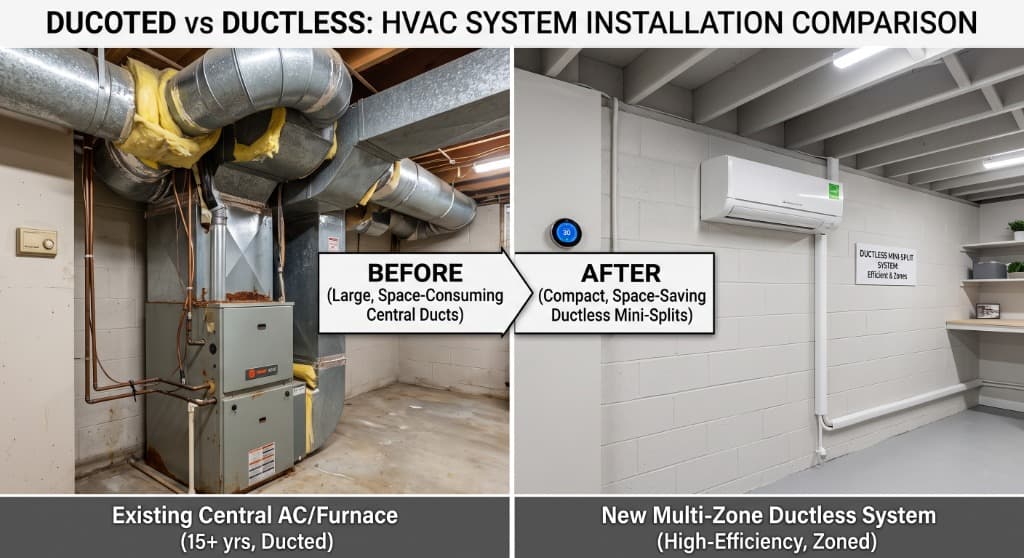
Ducted vs. Ductless Mini-Splits: Concealed Architecture & Multi-Zone Thermal Comfort
Architectural integration of mini-split systems: concealed slim-duct air handlers, branch box refrigeration, line set concealment, and individual room zoning.
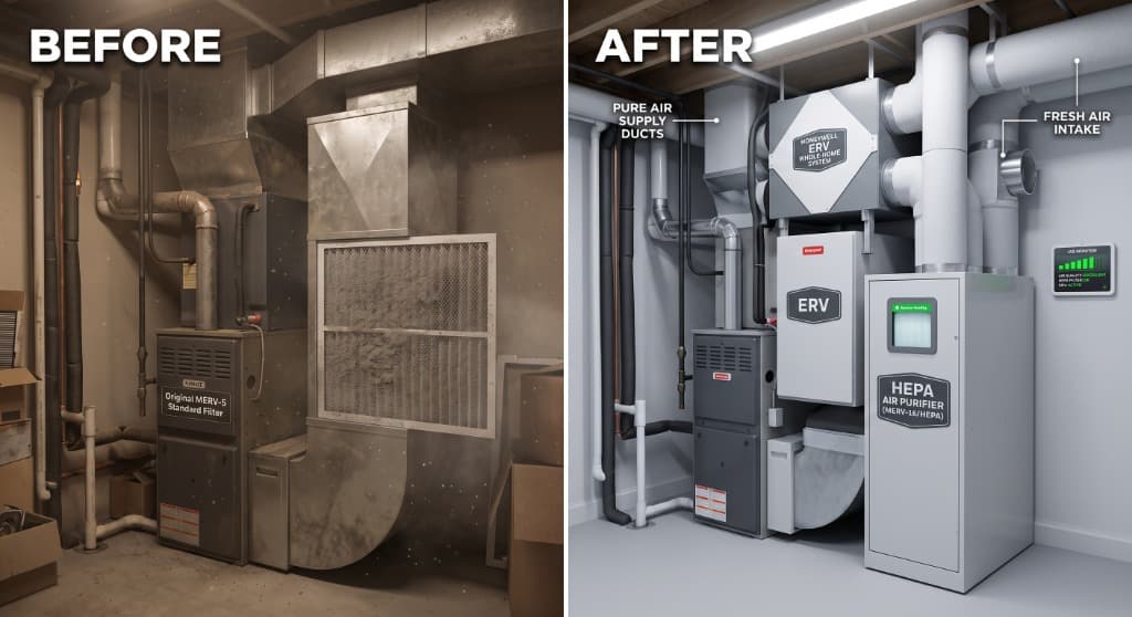
Indoor Air Quality (IAQ) Masterclass: MERV 16, True HEPA & Energy Recovery Ventilation
Eliminate PM2.5, wildfire smoke, and VOCs: whole-home HEPA bypass filtration, deep 5-inch MERV 16 media, ERVs vs HRVs, and active relative humidity control.